We are Authorized Channel Partners, Distributor, Dealer, Importer for Micro Detectors, Area Sensors from Pune, Maharashtra, India.

Introduction
Optoelectronic scanners are not covered by the provisions of EN 60947-5-2 and the following details only refer to common parameters. The technical terms of the paragraph headings reflect those used in the wording of this legislation, whilst those in italics are synonyms. The specifications listed relate to the nominal perfor-mance envisaged by said legislation and apply to products whose technical specifications do not include a specific figure.
Operating Principle
Type-T Optoelectronic scanners are made up of two elements; an emitter and a receiver. The emitter has an optical unit that consists of an array of photoemitters which emit a series of narrow luminous pulses to the receiver in a consecutive well-defined manner. Luminous radiation is generated by a solid- state source made up of high-performance long-lasting semiconductor elements. This radiation can be from outside the visible band. The receiver has an optical unit which is made up of an array of photoreceivers which correspond geometrically to those of the emitter. The luminous radiation reaching the photoreceivers is converted to an electric signal, amplified and processed in order to drive receiver output elements. As there is synchronous reading of the luminous pulse, a synchronous signal must be transmitted between emitter/receiver. Detection occurs when the path of the beam is interrupted by the presence of an opaque object.
Parallel-Ray Scanning
Every pulse emitted by a single element of the emitter array must be synchronously read by the corresponding element of the receiver array so that the single pair can be considered in light state. Every single emitter/receiver pair only controls its own axis of conjunction. Scanning determines an area crossed by parallel rays. Using parallel rays enables precise information to be obtained regarding size and position of target object.
Cross-Ray Scanning
Every pulse emitted by a single element of the emitter array must be synchronously read by the corresponding element of the receiver array, and by a variable num-ber of other receivers positioned on either side of the central one, so that the single pair can be considered in light state (i.e. path of beam completely clear). Every single emitter/ receiver pair controls a range of axes which originate from the emitter and reach an array of receivers. Scanning determines an area crossed by cross rays in a complex manner. The number of lateral receivers involved in reading the single emitter varies according to the range of the particular model. Every emitter must illuminate various receivers and can only do so if the optical-beam angle is sufficient for a certain distance. The number of receivers enabled can also vary during scanning. In extreme cases the two emitters on the edge of the array may only illuminate the internal lateral receivers because the external ones do not exist. Another case in particular is when single emitters must always illuminate all the receivers. This operating mode is simple to manage but requires large beam angles. Operating with cross rays does not enable precise information to be immediately obtained regarding size and position of target object, but merely reveals its pre-sence.
Synchronising Scanning
It is the function which allows a single element of the receiver array to be enabled to read only at the moment in which the luminous pulse is sent by the corresponding emitter element. The synchronisation serves to determine a strict relationship between corresponding emitter and receiver so as to reduce the effects of interference from other signals. With type T parallel-ray scanning sensors used for determining size and position of objects, the synchronisation must be realised by connecting a cable between emitter and receiver. With sensors that are only used for detecting the presence of an object, the synchronisation can be sent optically. Usually an emitter is added to the receiver array sends synchronisation message to an additional receiver in the emitter array. Alternatively, timing techniques can be used for autosynchronisation of the receiver, thus eliminating the need for cabling between emitter and receiver. Devices also exist whose arrays of optical elements alternate between emitters and receivers that pass the optical pulses on to each other. This type of solution is another which does not require cable synchronisation and cannot be used for pinpointing position and size of objects.
State Of Area
To define the state of the area or the single elements, reference must be made to the light/dark condition of the receivers. The dark condition is determined by the presence of an opaque object that blocks the path of the rays. The light condition is on the other hand determined by the fact that the path between emitter and receiver is clear.
General Description
The area sensors are composed of two elements: an emitter and a receiver element. The optical part is composed of an array of synchronized photoelements in order to avoid mutual interference. The main characteristics are:
• Istance between emitter and receiver (D): it indicates the operating distance between the emitter and the receiver;
• Optical beams space (BS): it indicates the spacing that exists between the optical axes of the single elements;
• Optical diameter (BD): it indicates the diameter of the output optical lens of the single element;
• Optical elements number (BN): it indicates the number of elements that composes the array;
• Blind zone (X): it indicates the zones near the emitter and the receiver where the resolution is less than the maximum one. This zone is properly related to the distance (D) between the emitter and the receiver: X = 0,06 x D
• Area height (AH): it indicates the height of the area selected by the optical beams: AH =[BS x (BN - 1)] + BD
• Resolution (R): it indicates the minimum dimensions of the target that it is possible to detect: R = BS + BN. Utilising cross-ray functions the resolution of the minimum detectable target increases (with blind zones exclusion);
• Analogical voltage output (VOUT) V it is an available It on the analogical voltage output properly related to the number of occupied / free optics:
NO configuration: VOUT = (10 / BN) x (number of occupied optics)
NC configuration : VOUT (10 / BN) x (number of free optics)
• Analogical current-type output (IOUT) V it is an available value on the analogical current-type output properly related to the number of occupied / free optics:
NO configuration: lOUT = (16 / BN) x (number of occupied optics) + 4
NC configuration: lOUT = (16 / BN) x (number of free optics) + 4
Blanking Function
If enabled some rays are turned off. This means that one or more areas are inactive; this can be useful in specific applications.
|
||||
Compact sensors with plastic housing; 6mm to 30 mm pitch; crossed beam detection up to 90 mm height; maximum sensing distance 6m. Atex models 3 GD and GD available; wide range of special models |
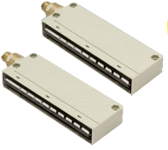 |
|||
|
||||
Compact Sensors in aluminium, height varying form 160 mm to 960 mm; crossod or parallel beams; up to 6 moperating distance; 5, 10 and 20 mm pitch; smallest detectabel object 1.5 mm; digiral and analogue output; teach adjustment; optical and cable synchronization |
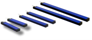 |
|||
|
||||
Aluminium housing; controlled height 70 mm; 0.3 m to 4.5 m sensing distance range; smallest detectable object 2 mm; red polarized emission; teach adjustment. Model with IO-LINK technology |
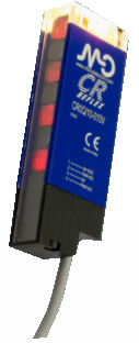 |
|||
|
||||
Withour housing; controlled height 140 aned 160 mm; up to 2 m sensing distance range; 10 mm pitch; axial or radial optics; maximum resolution 5 mm; trimmer adjustment; tropicalization available. |
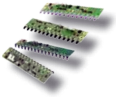 |
|||
|
||||
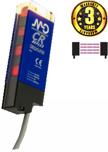
| • Area height controlled 69 mm • Maximum operative distance up to 4.5 m • Maximum object detection daim. 6mm • Two teach-in types: Fine and standard • Optical pitch 10mm • Protection degree IP67 • Blanking fuction |
 |
|||
|
||||
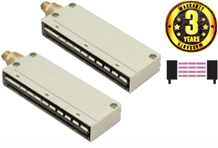
| • IP67 protection degree (IP69K special model) • Complete protection against electrical damages • Detection of objects with irregular shape • ATEX models available on request • LED Indicators • Crossed beams detection |
 |
|||
|
|||
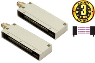
| • Controlled height 70mm • Operating distance up to 2 m • Microprocessor based circuit • Sensitivity adjustment • Strong cubic housing • Special version with metallic enclosure for high-duty use • Protection degree IP67 • Complete protection aginst electrical damages |
 |
||
|
|||
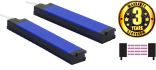
| • Total corossbeam through all the optics • Crossed area 160 and 320mm • Pitch 5mm and 10mm • Operating distance up to 3m (for 5mm pitch) and 6m (for 10mm pitch) • 2 digital NPN and PNP outputs (teach-in model available only with PNP logic) NO/NC configurable • Available with teach in adjustment or with external trimmer • High switching frequency to detection • Intrinsic synchronsim by cable (Teach-in models) |
 |
||
|
|||
| • Crossed beam (parallel beam for hight with more of 33 beams) • Optical Synchronzation • Pitch 5 mm and 10mm • Control hight up 480mm (pitch 5mm) and up 960mm (pitch 10mm) • Maximum Operating distance up to 3m (for 5mm pitch) and 6m (for 10mm pitch) • NPN and PNP digital outputs • For a correct use it is necessary to manually adjusment the emitter (accessory ST140) |
 |
||
|
|||
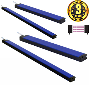
| • Parallel beams and floating crossbeams with variable amplitude • Synchronization by cable. Pitch 5, 10 and 20mm • Control height up 480mm (Pitch mm) and up 960mm (pitch 10mm and 20mm) • Maximum operating distance up to 3m (for 5mm pitch) and 6m (for 10mm and 20 pitch) • Digital outputs NPN and PNP; analogue current output (4...20mA) and analogue voltage output (0..10V), Mix outputs: digital PNP and analogue voltage output (0.10V) • Adjustment by teach-in, 3 levels of adjustment • Blanking function. Available analogue versions TOP BEAM |
 |
||
|
|||
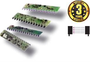
| • Complete protection against electrical damages • LED Indicators • Crossed beams detection • Without housing • 16 or 14 optics • Detection of goods in automatic vending machines • Detection of objects with irregular shapes |
 |
||
Read more products :


